
第1页 / 共55页
第2页 / 共55页
试读已结束,还剩53页,您可下载完整版后进行离线阅读
THE END
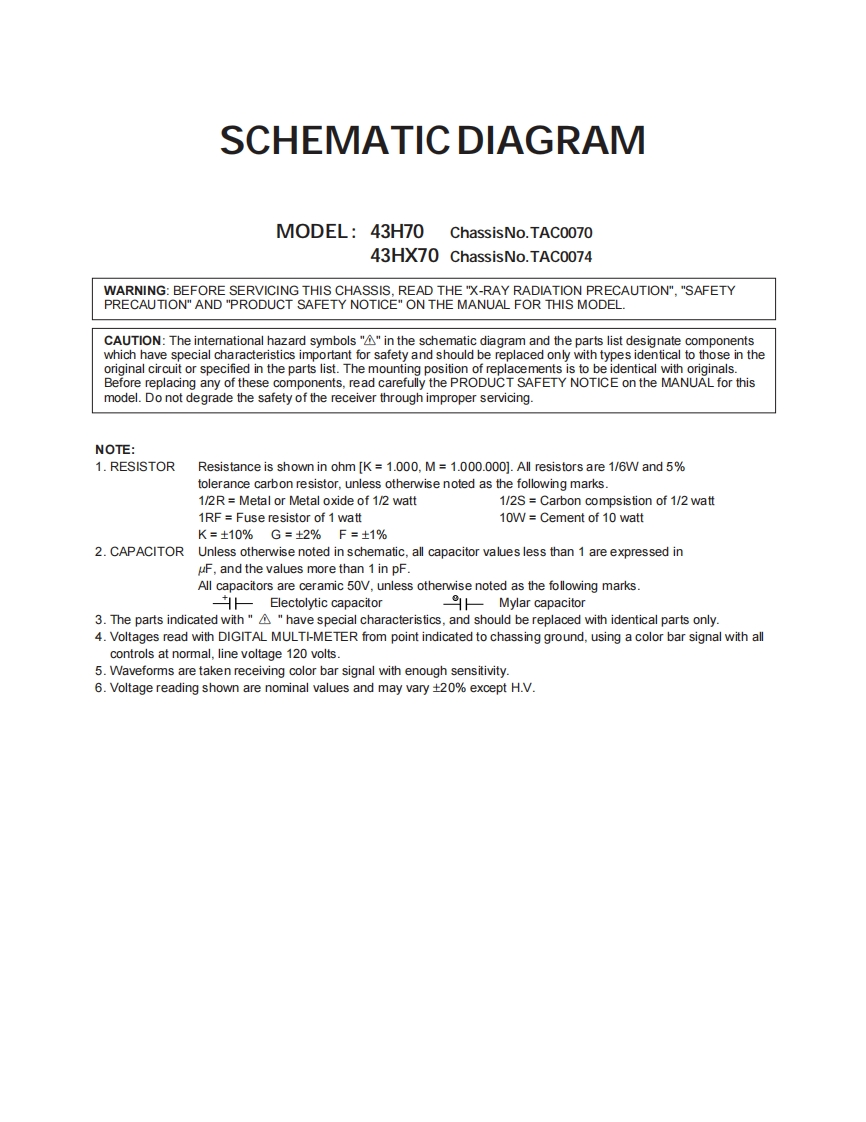
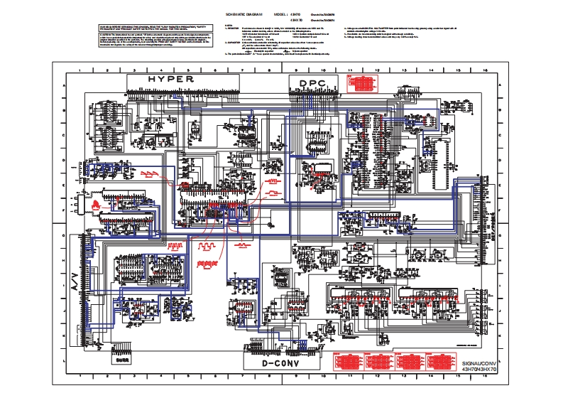
SCHEMATIC DIAGRAMMODEL:43H70 ChassisNo.TAC007043HX70 ChassisNo.TAC0074WARNING:BEFORE SERVICING THIS CHASSIS,READ THE "X-RAY RADIATION PRECAUTION","SAFETYPRECAUTIONAND"PRODUCT SAFETY NOTICE"ON THE MANUAL FOR THIS MODEL.CAUTION:The international hazard symbols"A"in the schematic diagram and the parts list designate componentswhich have special characteristics important for safety and should be replaced only with types identical to those in theoriginal circuit or specified in the parts list.The mounting position of replacements is to be identical with originals.Before replacing any of these components,read carefully the PRODUCT SAFETY NOTICE on the MANUAL for thismodel.Do not degrade the safety of the receiver through improper servicing.NOTE:1.RESISTORResistance is shown in ohm [K 1.000,M=1.000.000].All resistors are 1/6W and 5%tolerance carbon resistor,unless otherwise noted as the following marks.1/2R=Metal or Metal oxide of 1/2 watt1/2S Carbon compsistion of 1/2 watt1RF=Fuse resistor of 1 watt10W Cement of 10 wattK=±10%G=±2%F=±1%2.CAPACITOR Unless otherwise noted in schematic,all capacitor values less than 1 are expressed inuF,and the values more than 1 in pF.All capacitors are ceramic 50V,unless otherwise noted as the following marks.Electolytic capacitorMylar capacitor3.The parts indicated with""have special characteristics,and should be replaced with identical parts only.4.Voltages read with DIGITAL MULTI-METER from point indicated to chassing ground,using a color bar signal with allcontrols at normal,line voltage 120 volts.5.Waveforms are taken receiving color bar signal with enough sensitivity.6.Voltage reading shown are nominal values and may vary +20%except H.V.


请登录后查看评论内容