
第1页 / 共4页
第2页 / 共4页
试读已结束,还剩2页,您可下载完整版后进行离线阅读
THE END
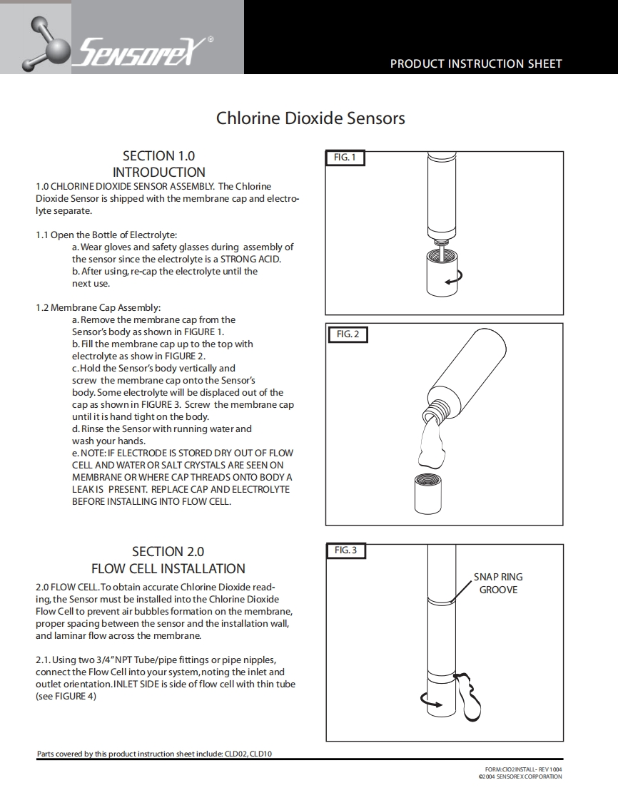
PRODUCT INSTRUCTION SHEETChlorine Dioxide SensorsSECTION 1.0FIG.1INTRODUCTION1.0 CHLORINE DIOXIDE SENSOR ASSEMBLY.The ChlorineDioxide Sensor is shipped with the membrane cap and electro-lyte separate.1.1 Open the Bottle of Electrolyte:a.Wear gloves and safety glasses during assembly ofthe sensor since the electrolyte is a STRONG ACID.b.After using,re-cap the electrolyte until thenext use.1.2 Membrane Cap Assembly:a.Remove the membrane cap from theSensor's body as shown in FIGURE 1.FIG.2b.Fill the membrane cap up to the top withelectrolyte as show in FIGURE 2.c.Hold the Sensor's body vertically andscrew the membrane cap onto the Sensor'sbody.Some electrolyte will be displaced out of thecap as shown in FIGURE 3.Screw the membrane capuntil it is hand tight on the body.d.Rinse the Sensor with running water andwash your hands.e.NOTE:IF ELECTRODE IS STORED DRY OUT OF FLOWCELL AND WATER OR SALT CRYSTALS ARE SEEN ONMEMBRANE OR WHERE CAP THREADS ONTO BODY ALEAKIS PRESENT.REPLACE CAP AND ELECTROLYTEBEFORE INSTALLING INTO FLOW CELL.SECTION 2.0FIG.3FLOW CELL INSTALLATIONSNAP RING2.0 FLOW CELL.To obtain accurate Chlorine Dioxide read-GROOVEing,the Sensor must be installed into the Chlorine DioxideFlow Cell to prevent air bubbles formation on the membrane,proper spacing between the sensor and the installation wall,and laminar flow across the membrane.2.1.Using two 3/4"NPT Tube/pipe fittings or pipe nipples,connect the Flow Cell into your system,noting the inlet andoutlet orientation.INLET SIDE is side of flow cell with thin tube(see FIGURE 4)Parts covered by this product instruction sheet include:CLD02,CLD10FORM-CO2INSTALL-REV100402004 SENSOREX CORPORATION

请登录后查看评论内容