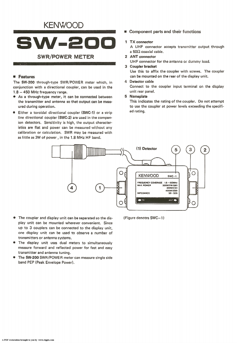
KENWOODComponent parts and their functionsV-21 TX connectorA UHF connector accepts transmitter output througha 501 coaxial cable.SWR/POWER METER2 ANT connectorUHF connector for the antenna or dummy load.3 Coupler bracketUse this to affix the coupler with screws.The couplerFeaturescan be mounted on the rear of the display unit.The SW-200 through-type SWR/POWER meter which,in4 Detector cableconjunction with a directional coupler,can be used in theConnect to the coupler input terminal on the display1.8-450 MHz frequency range.unit rear panel..As a through-type meter,it can be connected between5 Nameplatethe transmitter and antenna so that output can be meas-This indicates the rating of the coupler.Do not attemptured during operation.to use the coupler at power levels exceeding the specifi-Either a toroidal directional coupler (SWC-1)or a striped rating.line directional coupler (SWC-2)are used in the compan-ion detectors.Sensitivity is high,the output character-istics are flat and power can be measured without anycalibration or calculation.SWR may be measured withas little as 3W of power,in the 1.8 MHz HF band.(1)DetectorKENWOODSw0-1COVERAGE18-1500AM400w558IMPEDANCE50=520ANTThe coupler and display unit can be separated so the dis.(Figure denotes SWC-1)play unit can be mounted wherever convenient.Sinceup to 3 couplers can be connected to the display unit,one display unit can be used to observe a number oftransmitters or antenna systems.The display unit uses dual meters to simultaneouslymeasure forward and reflected power for fast and easytransmitter and antenna tuning.The SW-200 SWR/POWER meter can measure single sideband PEP (Peak Envelope Power).APDF resteraan hrough to you by www.rigpis.cm


请登录后查看评论内容